ASTM E1333 Standard Required Apparatus Introduction
1 Test Chamber:
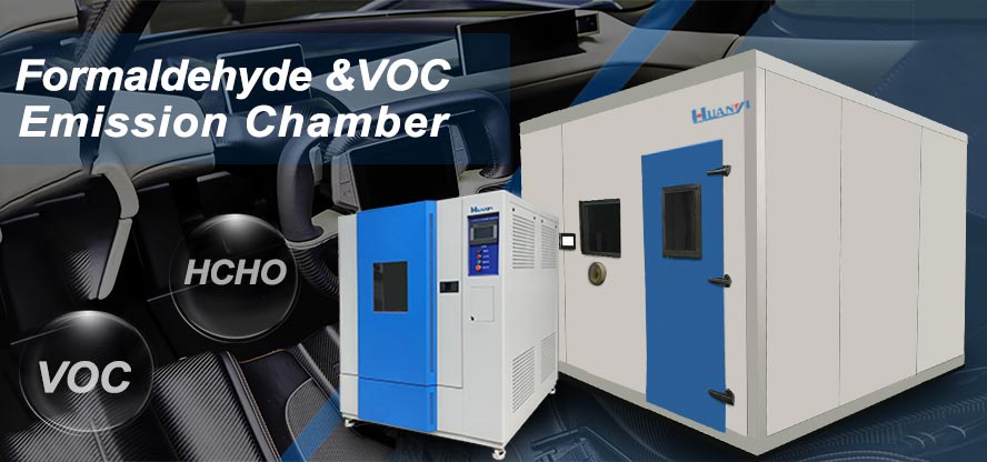
1.1 The interior volume of the chamber shall be a minimum of 22 m3(800 ft3). The interior of the test chamber shall be free of refrigeration coils that condense water and items such as humidifiers with water reservoirs as condensate will have the potential of collecting formaldehyde and thus influencing test results. The interior surfaces of the chamber shall be of materials found to minimize adsorption. (Stainless steel,aluminum, and polytetrafluoroethylene (PTFE) have produced recoveries of $95 % at a 0.4 ppm formaldehyde challenge concentration in air and have been found appropriate as chamber lining materials.) All joints except for doors used for loading and unloading specimens shall be sealed. Doors shall be self-sealing. The test chamber shall be equipped with metal specimen racks with dividers spaced a minimum of 150 mm (6in.) to support specimens on edge.
2 Make-Up Air:
2.1 The make-up air shall come from a filtered dust-free environment and not contain more formaldehyde than is capable of being measured considering the sensitivity of the analytical procedure using the sampling rate and volume of air as described in 10.2. This shall be accomplished by passing make-up air through a filter bed of activated carbon, activatedalumina impregnated with potassium permanganate, or other materials capable of absorbing, adsorbing, or oxidizing formaldehyde.
2.2 Make-up air for the chamber must pass through a calibrated, totalizing dry gas test meter or other airflow rate measuring device with calibration traceable to the National Institute of Standards and Technology (NIST). It is also acceptable to calibrate the airflow rate measuring device, as installed, using a tracer gas technique described in Test Method E 741. Air change rate per hour (AC/h) is calculated as (V2− V1) 4 ((t − 0) 3 chamber volume); where V2and V1are dry-gas test-meter readings in cubic metres at time, t (in hours),and time 0 divided by the chamber volume in cubic metres. The air-intake port and exhaust port shall be on different walls of the chamber and at different elevations. The chamber test shall be operated at a positive pressure of 1 Pa (0.004 in. of water) or greater as determined by a permanently mounted differential pressure device.10
1.3 Nonsparking Fan Sizing and Positioning—A nonsparking fan shall be used to circulate air within the chamber. The air flow shall be directed horizontally in the direction of the
chamber length above where the test samples are to be placed in the chamber. The fan shall be sized and positioned to achieve a uniform concentration in air of formaldehyde (within 0.03
ppm) as determined from a minimum of six air sampling locations. These locations shall be at three elevations, 0.3 m(12 in.) from the chamber floor and ceiling, and at a height between 1.3 and 1.5 m (51 and 59 in.); and at two vertical placements, 1⁄3 the chamber length from each end of the chamber and at chamber mid-width.
1.4 Air Sampling Ports—For testing, at least two airsampling ports shall be used, located at equal distance along the chamber length at an elevation between 1.3 and 1.5 m (51and 59 in.) and shall be placed at least 0.6 m (24 in.) from any interior wall. The sampling lines shall be of materials found to minimize adsorption such as stainless steel, PTFE and aluminum, securely fixed to supports during the test, and shall be as short as possible. The length of the sampling line outside the chamber shall not exceed 6 m (20 ft).
2 Examples of acceptable reagents, materials, and equipment are provided in Appendix X1.
DONGGUAN HUANYI INSTRUMENTS TECHNOLOGY CO., LTD


